In the offer of smart home system Grenton, you can find a LED RGB driver designed to control the tricoloured stripes/tapes/modules. Thanks to open Granton system logic, you can easily adapt system logic to controlling uni-coloured LED stripes. Thanks to such solution, with the use of one LED RGB module you can control three independent uni-coloured LED circuits. The below instruction includes the tips concerning the preparation of controlling one, uni-coloured LED circuit in the scope of control on the on/off basis (button click) and setting the light intensity (hold of the button).
To realize the below functionality, you will need:
- CLU central unit
- LED RGB module
- DIGITAL IN module, GRENTON SMART PANEL OLED or GRENTON TOUCH PANEL
- The environment for creating the system logic - Object Manager
Realizing the above functionality will require the creation of:
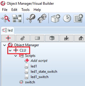
- scripts - in the exemplary project named:
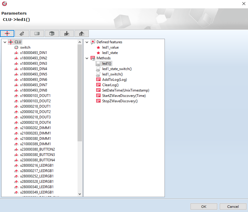
- led1 - support of dimming and brightening LED circuit,
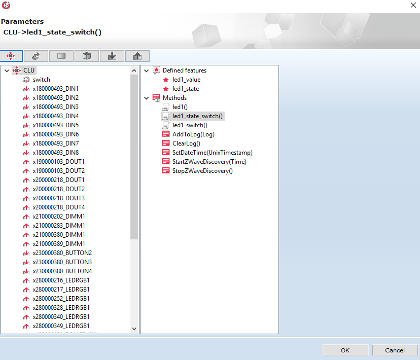
- led1_state_switch - the change of the condition (flag) of the LED circuit,
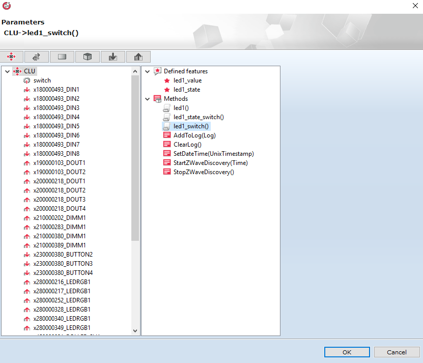
- led1_switch - support of controlling LED circuit with the on/off basis
- Global variables – in the exemplary project named:
- led1_value - the current value of LED circuit light intensity
- led1_state - the current condition of the LED circuit
The configuration of CLU central unit
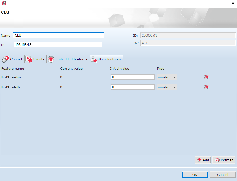
1. Double-click on CLU icon to enter the module settings:
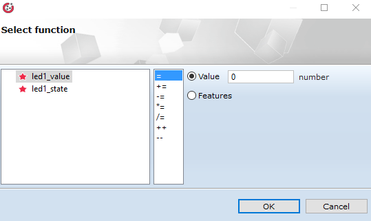
2. Go to “User features” tab and create the global variable of number type:
- led1_value - the current value of LED circuit light intensity – the initial value 0
- led1_state - the current LED circuit condition – the initial value 0
Logic configuration
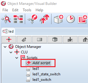
1. Create work managing scripts. You can find the information on how to create scripts in Grenton system HERE . To fill support of functionality, the below scripts will be used:
- led1 - support of dimming and brightening LED circuit,
- led1_state_switch - the change of the condition (flag) of the LED circuit – necessary both for the functionality of dimming and on/off controlling
- led1_switch - support of controlling LED circuit with the on/off basis.
2. Prepare script led1 by the use of Components tray on the right side of the Object Manager software window. The connections and logic conditions between created function blocks should look like as shown on the below scheme:
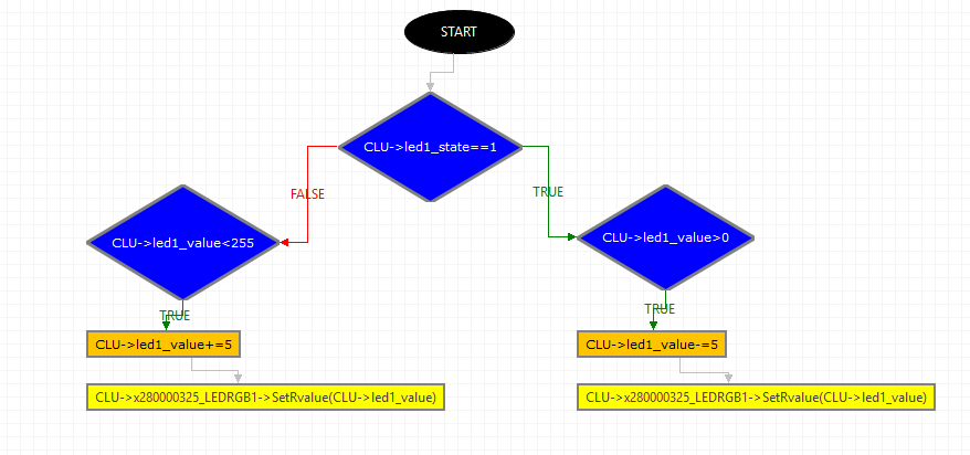
Below there is a full list of the components and the procedure of creating them.
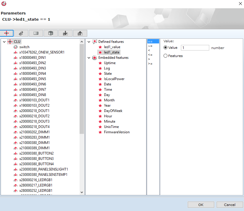
- Condition > CLU > Defined Features: led1_state > Logic Condition: "==" > Value: 1
Checking if the condition of the LED circuit is 1 (an assumption, checking if a given circuit is set)

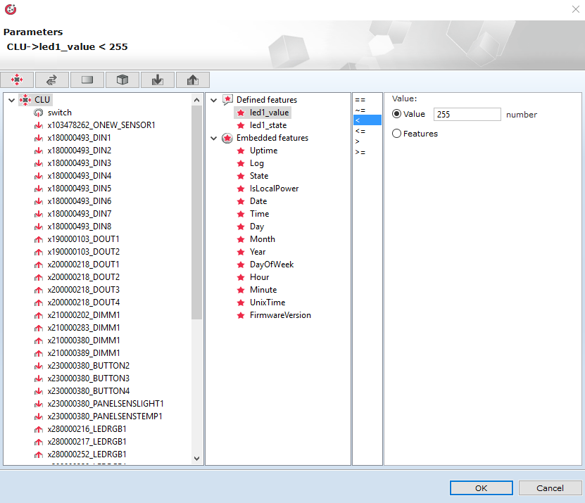
- Condition > CLU > Defined Features: led1_value > Logic Condition: "<" > Value: 255
Securing from crossing the maximally permissible value of intensity received wy the output of the Grenton module (entering a higher value, will set it on 0)
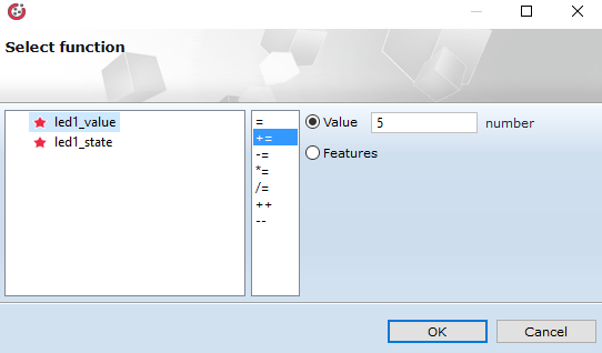
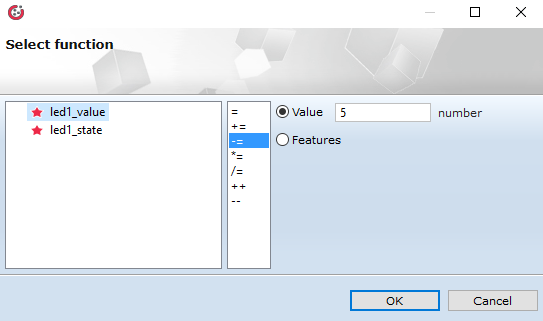
- Operations on the variables > led1_value > "+=" > Value: 5
Incrementing of the value of intensity of ced1 circuit to value 5 – brightening
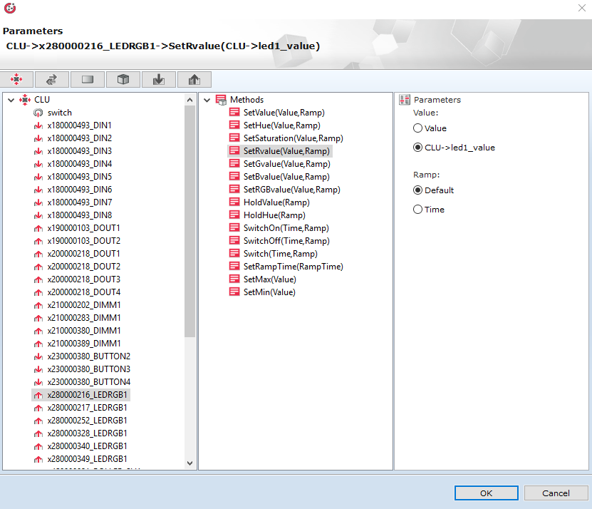
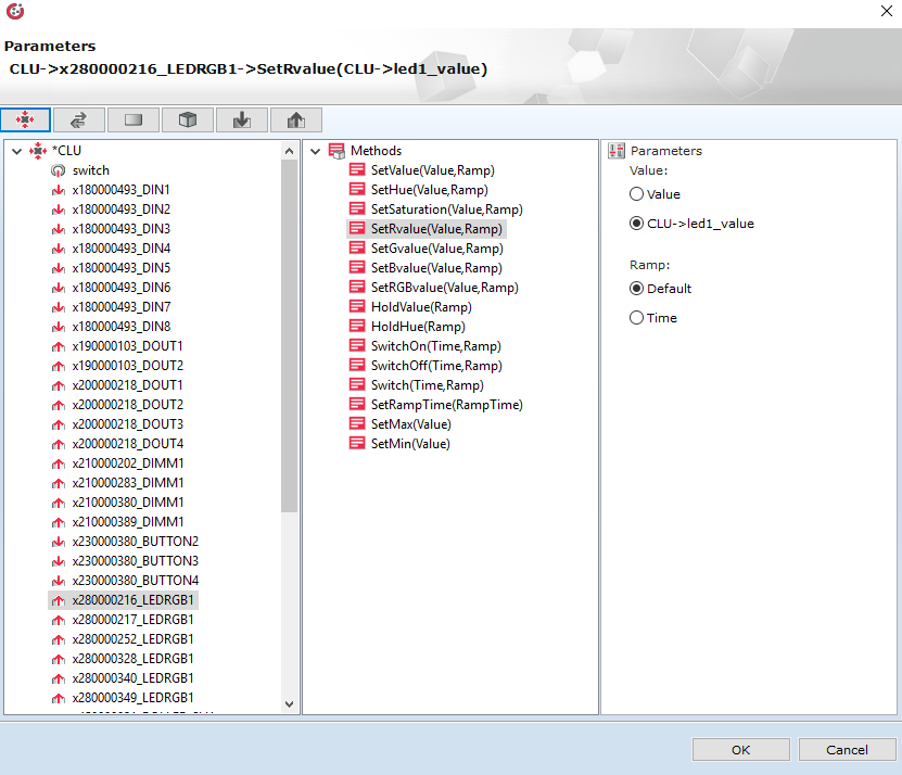
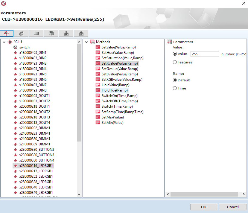
- Action > LEDRGB > Methods: SetRvalue(Value,Ramp) > Parameters: Time > Value: Features > CLU > Defined Features: led1_value
Assigning variable led1_value to the R channel. Ramp parameter (the time of increasing) was set as default (you can change it in Inbuilt module features).
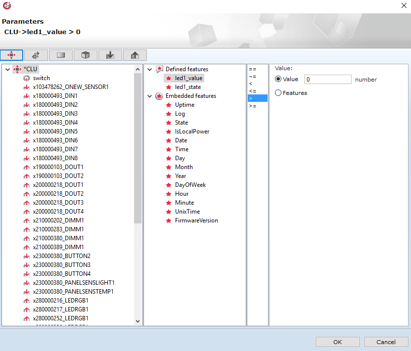
- Condition > CLU > Defined Features: led1_value > Logic Condition: ">" > Value: 0
Securing from crossing the minimally permissible value of intensity received wy the output of the Grenton module (entering a lower value, will set it on 255)
- Operations on the variables > led1_value > "-=" > Value: 5
Decrement of the value of led1 circuit intensity to value 5 - dimming
- Action > LEDRGB > Methods: SetRvalue(Value,Ramp) > Parameters: Time > Value: Features > CLU > Defined Features: led1_value
Assigning variable led1_value to the R channel. Ramp parameter (the time of increasing) was set as default (you can change it in Inbuilt module features).
ATTENTION! If the increase of intensity is too fast, it should be reduced by the value with which the variable led1_value is incremented and decremented. If this value is too slow, this value should be increased.
The above logic in text mode is presented as below:
if(not (CLU->led1_state==1)) then

if(CLU->led1_value<255) then
CLU->led1_value=CLU->led1_value+5
CLU->x280000325_LEDRGB1->SetRvalue(CLU->led1_value)
end

else

if(CLU->led1_value>0) then
CLU->led1_value=CLU->led1_value-5
CLU->x280000325_LEDRGB1->SetRvalue(CLU->led1_value)
end

end
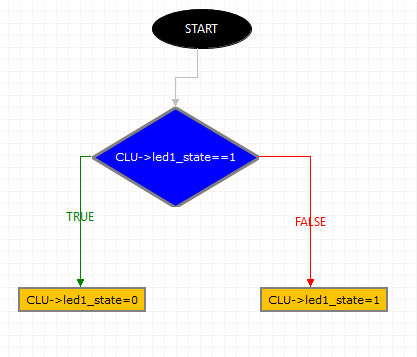
3. Prepare led1_state_switch script by the use of Components tray on the right side of the Object Manager software window. The connections and logic conditions between created function blocks should look like as shown on the below scheme:
Below there is a full list of the components and the procedure of creating them.
- Condition > CLU > Defined Features: led1_state > Logic Condition: "==" > Value: 1
Checking if the status of the LED circuit is 1 (an assumption, checking if a given circuit is set)
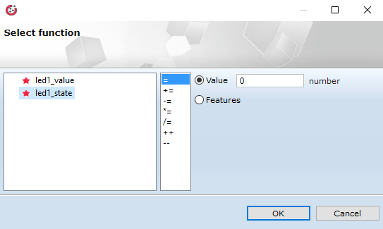
- Operations on the variables > led1_state > "=" > Value: 0
Setting LED circuit on 0 (off)
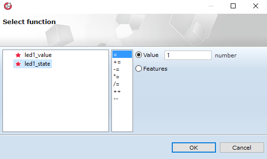
- Operations on the variables > led1_state > "=" > Value: 1
Setting LED circuit on 1 (on)
The above logic in text mode is presented as below:
if(not (CLU->led1_state==1)) then

CLU->led1_state=1

else

CLU->led1_state=0

end
4. Prepare led1_state_switch script by the use of Components tray on the right side of the Object Manager software window. The connections and logic conditions between created function blocks should look like as shown on the below scheme:
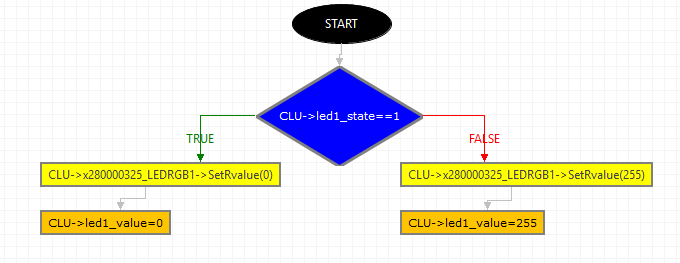
Below there is a full list of the components and the procedure of creating them.
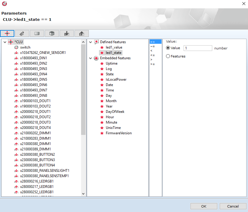
- Condition > CLU > Defined Features: led1_state > Logic Condition: "==" > Value: 1
Checking if the status of LED circuit is 1 (in assumption, checking if a given circuit is set)
- Action > LEDRGB > Methods: SetRvalue(Value,Ramp) > Parameters: Time > Value: 0
Assigning value 0 to the R channel (switching off the circuit). Ramp parameter (the time of increasing) was set as default (you can change it in inbuilt module features).

- Operations on the variables > led1_value > "=" > Value: 0
Setting the value of light intensity of LED circuit on 0 (off) – switching the value for possible brightening of the circuits
- Action > LEDRGB > Methods: SetRvalue(Value,Ramp) > Parameters: Time > Value: 255
Assigning value 255 to the R channel (switching on the circuit). Ramp parameter (the time of increasing) was set as default (you can change it in inbuilt module features).
- Operations on the variables > led1_value > "=" > Value: 255
Setting the value of light intensity of LED circuit on 255 (on) – switching the value for possible brightening of the circuits
The above logic in text mode is presented as below:
if(CLU->led1_state==1) then

CLU->x280000325_LEDRGB1->SetRvalue(0)
CLU->led1_value=0

else

CLU->x280000325_LEDRGB1->SetRvalue(255)
CLU->led1_value=255

end
The configuration of input devices
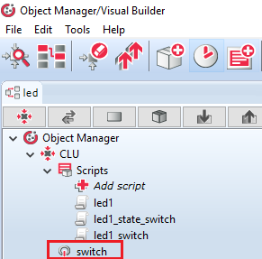
1. Double click on the input switch icon to go to the module input settings:
2. Go to "Embedded features" tab and set the Initial Values of the Mode, HoldDelay and HoldInterval parameters as below:
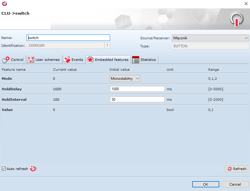
- Mode feature defines the mode of input/button action – this parameter must be marked as Monostable,
- HoldDelay feature defines time, after which the system will begin to recognize the given impulse (signal) as OnHold event,
- HoldInterval feature defines the interval in which OnHold event will be executed.
3. Go to the “Events” tab and assign corresponding commands to the below events.
- for OnSwitchOff events
- for OnHold event – it will be responsible for supporting dimming and brightening. An OnHold event is an event executed cyclically by the time set in HoldInterval feature
- for OnClick event – it will be responsible for controlling on the on/off basis
ATTENTION! Setting HoldInterval time lower than 100 will cause in setting the time of this parameter as 0, what will cause invalid work of the system.
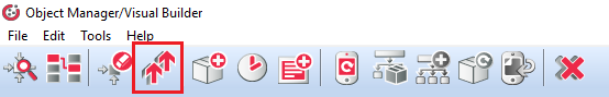
Sending configuration to the system
1. After entering all changes, send the configuration to CLU by using the below button on the toolbar:
The support of a next LED circuit with the use of the same module will require the control by the use of a next LED RGB G or B module. To do this, for the next LED circuit the above instructions should be followed analogically.
