TF-Bus Connectors Scheme v1.0
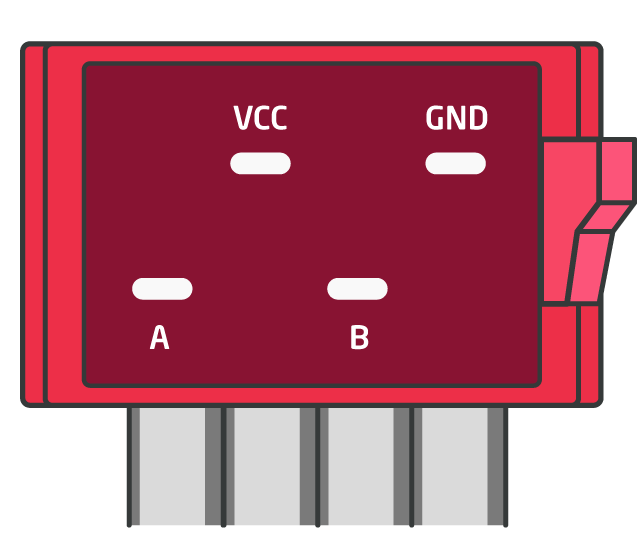
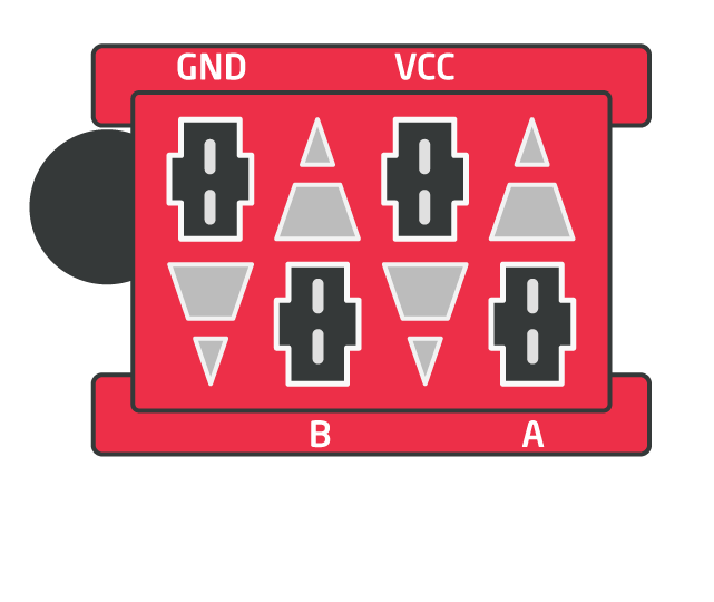
The graphics below, presents wire place of TF-Bus Connector.
- A and B - communication wires,
- Vcc and GND - bus power supply.
For male plug:
For female plug:

The graphics below, presents wire place of TF-Bus Connector.
For male plug:
For female plug: