For the correct work of system, a DC power supply with a voltage of 5V is required for Grenton modules. We can supply the system in two ways:
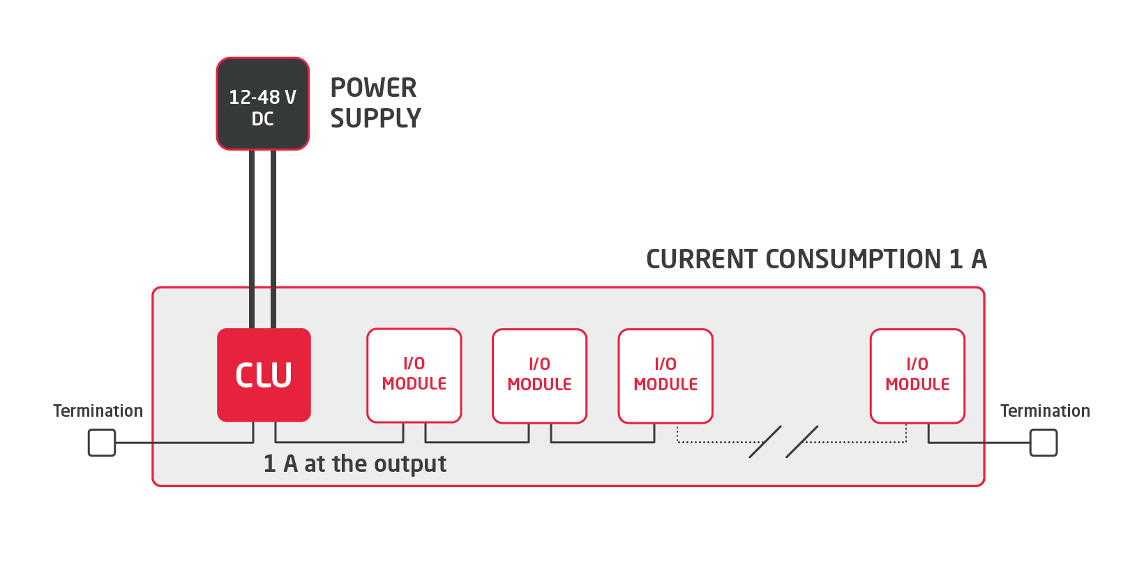
- With 12-48 V DC power supply connected to screw terminals on CLU
- With 5 V DC power supply connected to the bus
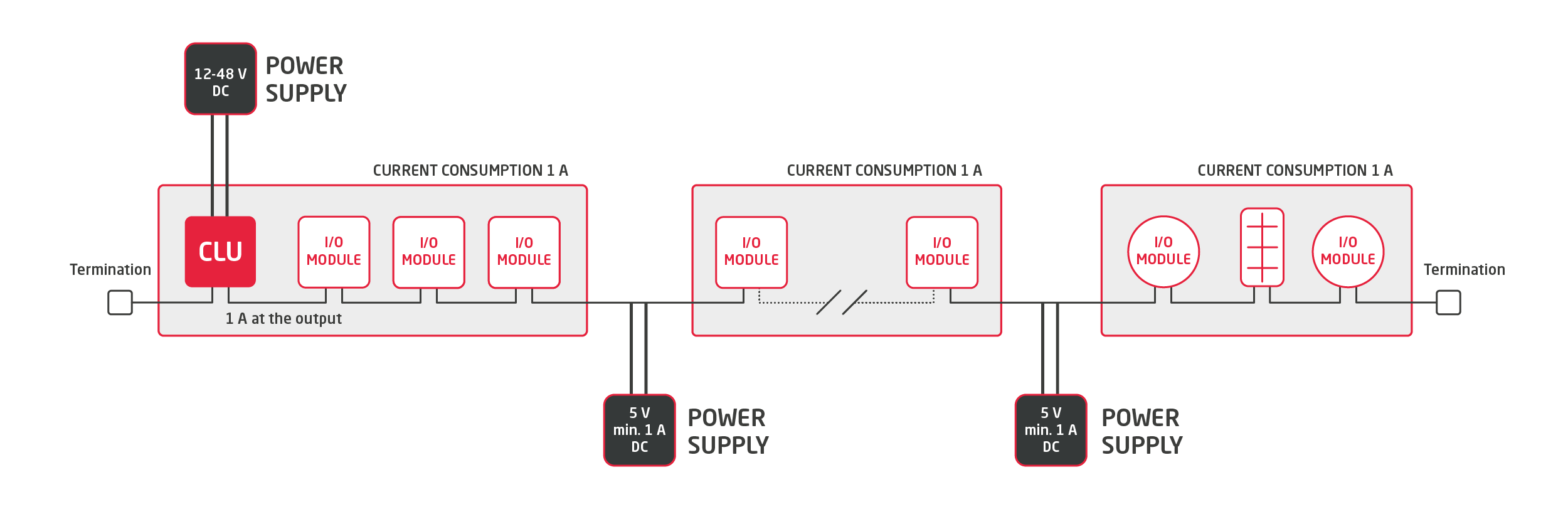
Both above solutions can be applied in parallel to each other, i.e. system bus supplied both from 5 V DC power supply connected to TF-Bus and by connecting the 12-48 V power supply to central unit CLU.
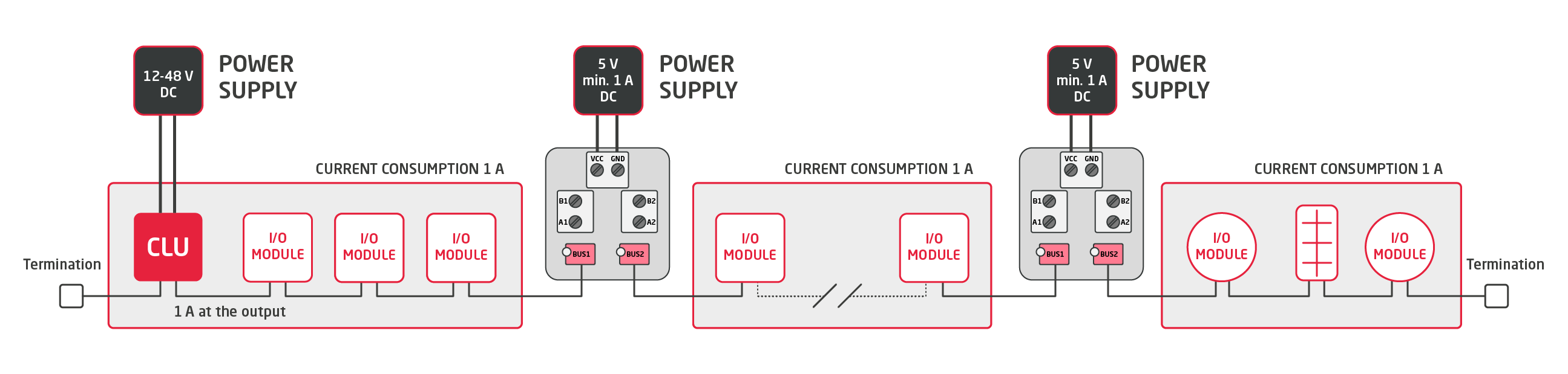
While connecting 12-48 V power supply to the socket locates in the upper part of the central unit (CLU) there is 5 V DC current of 1 A amperage is disposed on the bus.
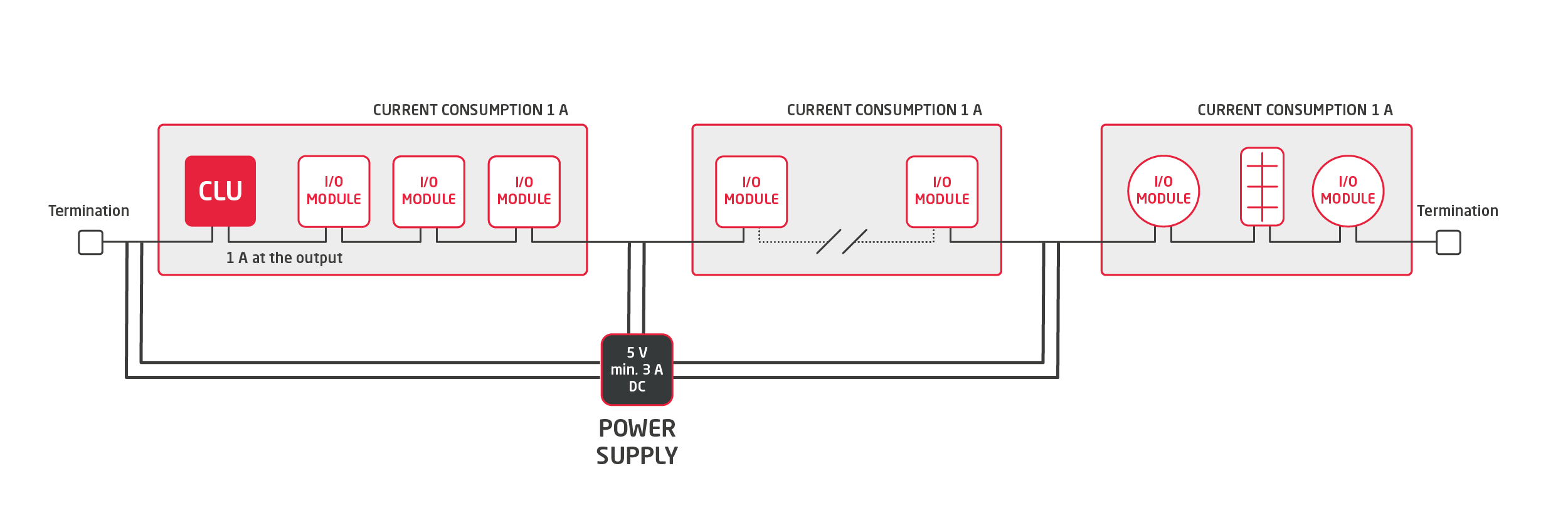
If the current demand of the devices connected to the bus is greater than 1A, then the bus should be locally supplied with the additional power supplies so that the additional power supplementation is realized by every 1A (sectional current demand). This limitation results from the cross section of the applied bus wires. The scheme of such connection is presented by the following graphics:
The second method is supplying the system only by the bus. In this case, the bus unit is supplied directly from the TF-Bus:
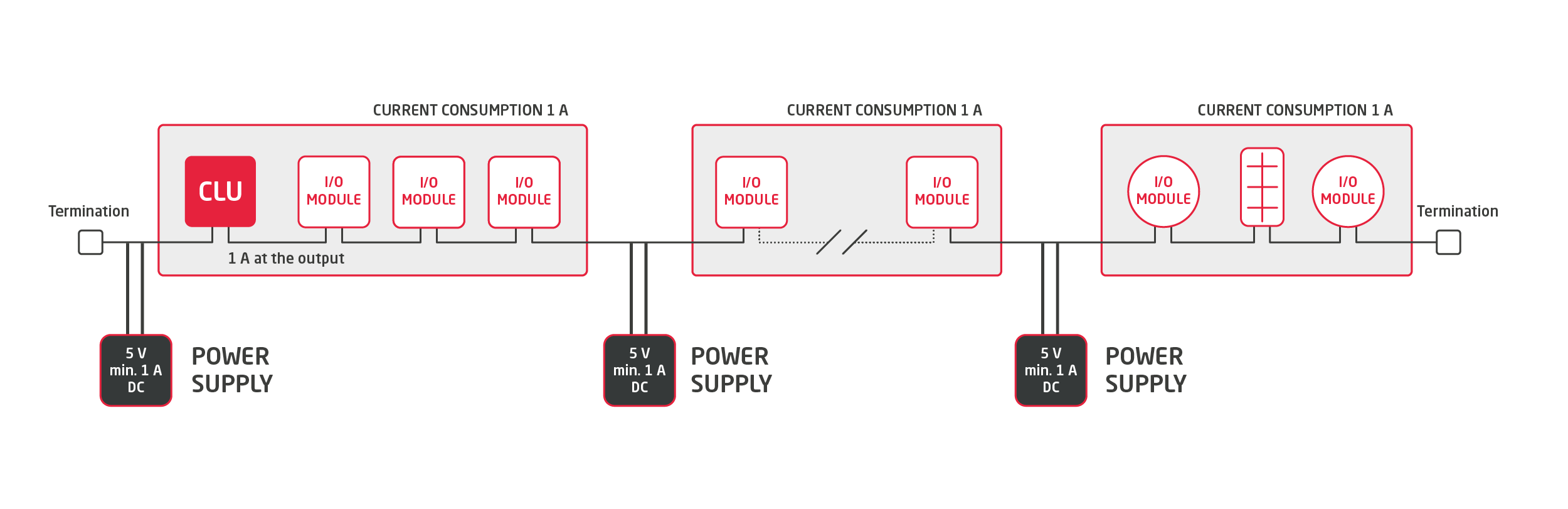
Additional power supplementation of the bus may be also realized from a single power supply with a bigger current performance, selected on the basis of the maximal current demand of devices connected to the system and taking into account the voltage drops resulting from the length of the bus wire.
The bus can be supplied also by the direct soldering of Vcc and GND wires of the power supply to the corresponding wires in the bus connector or by the use of ARK adapters (recommended).